MikroTik configuration for point-to-point
Mikrotik equipment configuration is made through the program called Winbox. You can download it via the link: http: //router_address/winbox/winbox.exe (where router_address is device address, respectively). Also you can go to the device through the web interface and download winbox through the link. The first thing we do - reset factory settings.
Reset Mikrotik to factory settings
1. If you are connected to the device for the first time, the corresponding window titled RouterOS Default Configuration will appear immediately and you need to reset the settings by clicking on Remove Configuration.
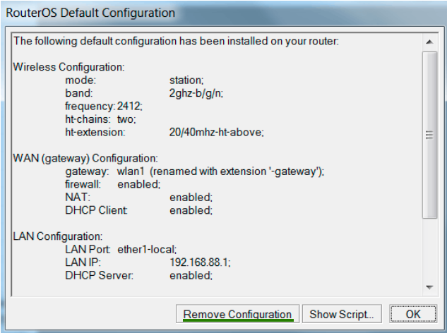
2. If you have already visited the device once, the default window won’t appear. Go to the New Terminal menu and with the system reset-configuration command restart the device (after reboot window with settings reset will appear).
Or go to the System menu, then - into Reset Configuration. Then tick No Default Configuration and click on Reset Configuration. Factory configuration had reset.
BRIDGE Settings
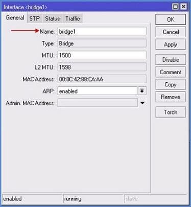
Adding ports so the traffic can be transmitted through MikroTik equipment on a wired and WiFi interface. Otherwise, our devices will only "talk" to each other. To do this, click + button in the Bridge menu (opens a window like in the image below), assign name for the bridge and click OK.
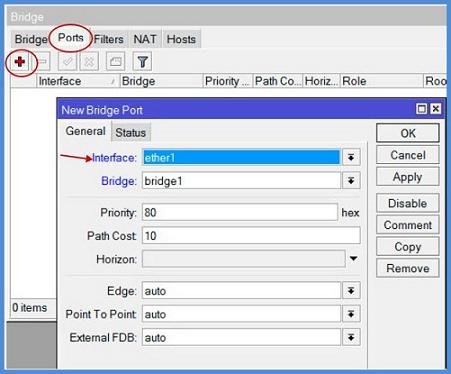
Go to the Ports tab, click on + and add the Wlan1 port on Interface line. On the Bridge line chose our previously createdbridge1. Hit OK. Click + again and create Ether1port:
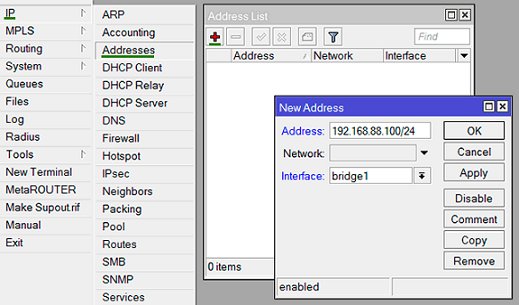
Assign IP-address for the bridge:
IPmenu => Adresses submenu => "+" button, enter bridge address and subnet mask. Filling lines after Network is optional.
Configuration in the Wireless menu
Select Wireless, then open Wlan1.
1. Wireless tab settings
Wireless interface parameters are set here:
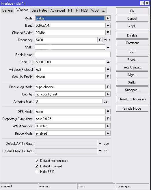
Mode - Now we are interested in:
- Bridge - BS mode for point-to-point
- AP Bridge - BS mode for point-to-multipoint.
There is also a mode for client workstations:
- Station - settings for a client device.
- Station WDS - settings for a client device with WDS support. (recommended to use on the client.)
Band - The first part of the value, up to a dash - is the frequency of operation, the second - supported standards. For the standards it is recommended to select only-N value, to raise the maximum speed.
On the client device, you can choose several options for standards, for example, expose 2GHz-B / G / N, then when you change settings on the BS customers you will reconnect automatically.
Channel Width - By default, put 20MHz. If you plan more than 100 Mbit / s and using Gigabit device - then you can use a 40MHz bandwidth.
Frequency - Select from the list or write manually.
SSID - The network name. It will be seen by the subscriber units.
Radio Name - The device name. For example, kv_Titova_d_8.
Scan List - Default, while using only the standard channels. You can specify a single frequency, multiple (separated by a comma), the range (with a dash), and can be combined. For example, a value of "2424, 2300-2500" will mean that the first device will start searching for the BS on the channel in 2424, in the absence of a response will go to the range 2300-2500, and will be looking there.
Wireless Protocol - equipment working protocols.
- 802.11 - normal protocol wi-fi, suitable for connection to a customers base station with laptops or USB adapters.
- Nstreme - the old polling protocol. If it is exposed in the settings, to the BS will connect only devices that support it.
- NV2 - the last polling protocol. We use it. Again, the connection will be available for devices that support this type of protocol. With laptop or USB adapter connection is impossible.
- Any - This mode is exhibiting for the subscribers. This enables connection to the BS at any exposed modes.
Security Profile - Normally - default.
Frequency Mode - Selection Mode for available frequencies and capacities
- Manual Txpower - This mode provides the ability to manually change the settings of the radio signal strength.
- Regulatory Domain - selection of operating mode with the parameters of power and frequency allowed for the particular country.
- Superchannel - In this mode, the power can be changed, as well as to use all available frequencies.
Country - Select a country to determine the list of frequencies that it is available.
Antenna Gain - Often not used, put "0" in field.
WMM Support< b> - Radio priorities.
Bridge Mode - Always - enabled.
Default Authenticate - When exposed tick – all devices can connect, tick removed - only those that are in the Allow list.
Default Forward - Exposed tick - restriction of data exchange between the connected client devices. This setting only works in 802.11 mode for laptops and devices without WDS support.
Hide SSID Exposed tick hides the name of the network (the network does not appear in the list if scanned). To connect, you must manually register the name of the client device.
2. Settings on the Data Rates tab
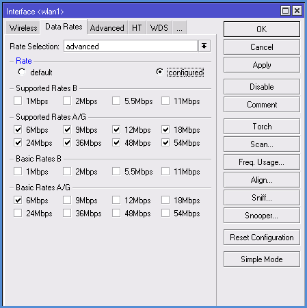
If we choose N-only mode for our devices, all the checkboxes on this tab will be removed. Other - see settings below.
Rate Selection - Put the Advanced for our best configuration for devices.
Supported Rates - remove the ticks so devices will be using only a high-speed standard G and N.
Supported Rates A / G Expose all ticks.
Basic Rates B - remove all ticks.
Basic Rates A / G - Install only 6 M.
3. Settings in the Advanced tab
Max Station Count - The maximum number of client connections
Distance - The maximum distance to the subscriber stations
- Dynamic - the distance is determined automatically.
- Indoor - expose this value for data transfer indoors.
Noise Floor Threshold - The most common values are set ... -92 -107. You can also define it by yourself: to measure the noise level and reduce this figure by 5-10 units. For example: If the sound level -107, therefore, the value we put is -100.
Periodic Calibration - It is recommended to always include this option (enabled), so the device will automatically adjust to increase / decrease the noise level.
Calibration Interval - recommended to set for 10 seconds. Default is 1 minute.
Hw. Retries - The amount of data sent repeats unless the acknowledgment of receipt.
- Values between 1 and 5 - the speed of the connection is higher, but for users with poor signal connection stability gets worse (packet loss, frequent disconnections).
- Values between 5 and 10 - the golden middle.
- Values between 10 and 15 - the maximum guarantee delivery of data, but the problem network will slow down.
On this basis, for the base station preferably exhibit average values (5-7) and put the maximum channel-to-point - 15.
Hw. Protection Mode - Always put out RTS / CTS.
Adaptive Noise Immunity - It is recommended to activate the option AP and client mode for protection against interference when multiple base stations are close by.
Disconnect Timeout - The time period over which the client does not respond to the request, it will be disabled.
On Fail Retry Time - It is recommended to leave the 100 ms.
4. Settings in HT, HT MCS, WDS tabs
If our devices use MIMO (which is desirable since such equipment bandwidth is higher), then you need to pay attention to the appropriate setting antennas on the HTtab:
- HT Tx Chains - the receive channel, HT Rx Chains - the transmission channel. If you are using the MIMO, it is best to activate both antennas on reception and transmission (chain0, chain1). Of course, if there is only one antenna, then activate one channel.
- In the HT Guard Interval parameter ALWAYS put long, if you use the N standard for external links.
- HT Extension Channel - This parameter is used to add additional channels when using 40 MHz. Optimal values are established experimentally.
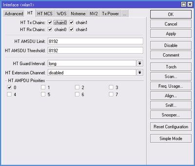
On the HT MCS tab it is recommended to leave the default values.
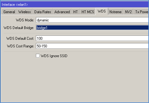
On the WDS tab we are interested in two parameters:
- WDS Mode - recommended to set mode Dynamic, while new customers bridge will be added automatically. In case of manually adding preferences, select Static.
- WDS Default Bridge - by default customers will be added to the specified field in the bridge. Therefore, we specify its name here: bridge1.
5. Settings in NV2 tab
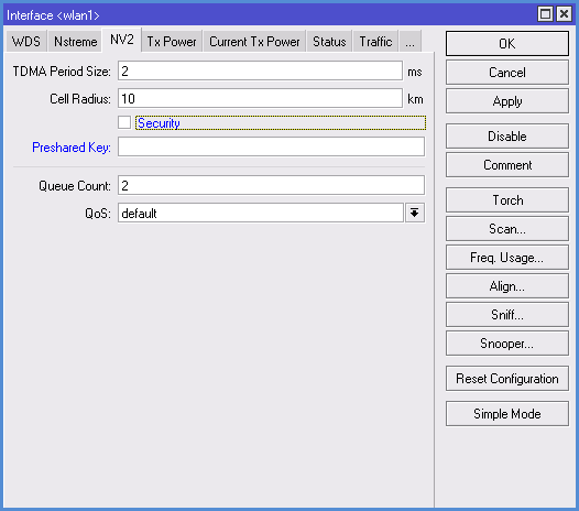
Here we set the parameters of the MikroTik NV2 protocol (by the way, setting NSTREME Protocol and the relevant tab we do not consider because it is outdated and almost never used).
- TDMA Period Size - the time of transmission. For the base station 5-7 is recommended, for radio bridge - 1-2. Lower the value in this field, smaller the transmission delay is, but the rate decreases. And vice versa - increasing the value will mean more speed, but increased delay. The optimum value is selected by experimenting.
- Cell Radius - here we expose the distance to the remote client
- Security - enable / disable encryption protocol through NV2 protocol. This is a completely separate encryption mechanism unrelated to the fact that we will adjust the Security Profiles tab.
- Preshared Key - security key for connection to network, set same for all devices.
6. Settings for TX POWER tab
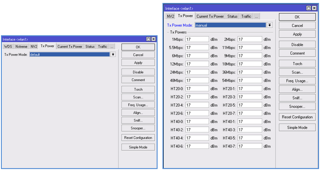
More often is set to Default. If you select Manual, the field with the settings will appear and you can manually adjust radio card power.
Encryption configuration
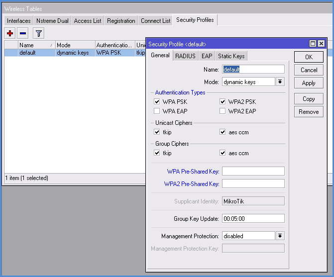
In the Wireless section, go to Security Profiles tab:
- Name - assign the encryption profile name.
- Mode - Select the encryption mode, often set Dynamic Keys.
- Authentication Types - put a tick on WPA PSK, WPA2 PSK or select both.
- Unicast Ciphers - Select the encryption algorithm. Recommended AES, because it supports radio card.
- Group Ciphers - the same settings as in the previous paragraph.
- WPA Pre-Shared Key - the code word for the WPA type of encryption. We put the same on all devices.
- WPA2 Pre-Shared Key - password for the WPA2 encryption type
Second device configuration
Most of the settings are identical, with the exception of:
- When you configure IP-addresses for the second point make it different from the first address.
- If you are configuring the wireless interface settings on the Wireless tab, specify: in the Mode - station wds, in the SSID - the name of the first point.
Views of connection compounds
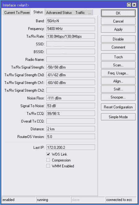
If we set up all correctly, you can see parameters in the Status tab:
Band - The frequency and standard of work points (Mode)
Frequency - The channel frequency of the device
Tx/Rx Rate - transmission and reception modulation
SSID - network name
BSSID - second device Mac address
Radio Name - second device name
Tx/Rx Signal Strenght - Signal level transmit / receive. If two antennas are used, the data is summed.
Tx/Rx Signal Strenght Ch0 - Signal level transmit / receive on zero antenna (channel)
Tx/Rx Signal Strenght Ch1 - Signal level transmit / receive on first antenna (channel)
Noise Floor - Noise level
Signal To Noise - the signal to noise ratio. Standard considered that values from 5 to 15 - low, 15 to 30 – average, 30 to 60 - high. Higher the value in this field - better.
Tx/Rx CCQ - channel transmit / receive quality.
- From 1 to 50 - bad
- From 50-80 - medium
- From 80-100 - good.
Distance - The distance to the second device
Router OS Version - Firmware version of the second device
Last IP - Last IP-address recorded in the device
WDS Link - Shows the work in WDS.
